
Trace scrap from loading to collection before choosing conveyors. A correctly sized shredder can still wait for feed or stop when discharge backs up. Scrap metal conveyors need a handoff specification across feeding, transfer and discharge. For each interface, record the material condition, receiver, route and stop response. Put the scrap mix and required line duty on the schedule before suppliers fix mechanical and control boundaries in a quote.
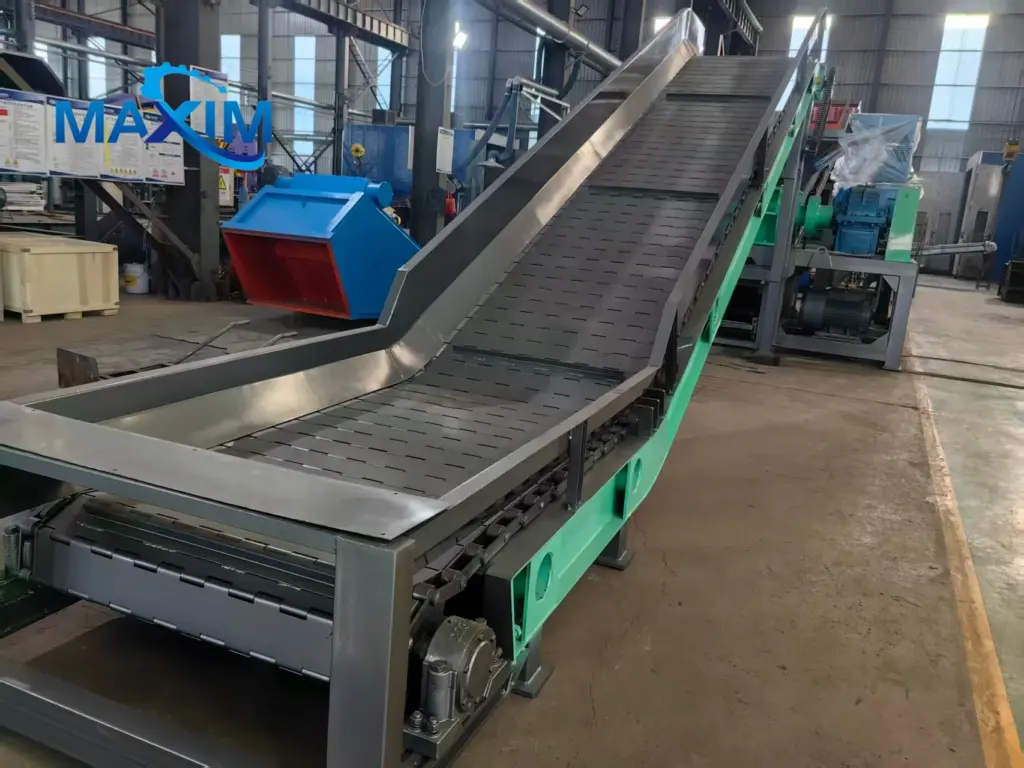
A long sharp piece may snag on a sidewall or chute; a dense bale presents a different load from loose sheet metal. The label “scrap” does not tell a supplier which will arrive. For the feed sheet, capture the largest piece's size, weight, shape and thickness, plus bulk density and contaminants. The same sheet should name the loading source: bucket, grapple, sorting station or feeder. These details determine what a belt, chain plate or other arrangement must handle in scrap metal conveyors.
Mark drop height, side containment and access for rejected pieces on the loading-zone drawing. Steady and batch loading need different peak-load assumptions; state the arrival pattern and hourly average. If a loader feeds the line, review impact and surface protection. For scrap metal conveyors, specify which sharp or oversize pieces must be sorted out and the assumed edge protection.
At the shredder, mark where the metal scrap conveyor delivers material, then give entry width, height, direction and elevation. Check whether pieces may bridge or arrive faster than the shredder accepts them. Show the chute, guards, access and supply limits on the interface drawing. Define when scrap metal conveyors must pause because the receiver is unavailable; leave detailed PLC logic to the controls package.

After the shredder, scrap metal conveyors carry reduced material toward separation; the receiver must take the flow. For an integrated scrap metal recycling production line, MAXIM machinery can configure feeding and discharge conveyors alongside a vibrating feeder, shredders, magnetic separators and eddy-current separators. The arrangement follows material and output requirements. Our review starts with the size leaving the shredder and what the next machine accepts.
Direct transfer may remove the loader if the shredder outlet matches the receiver. The drawing should answer a practical question: at the proposed inlet elevation, can the receiver handle the peak discharge, piece size and feed presentation? Check discharge trajectory. Even with scrap metal conveyors linking the machines, separator feed may fluctuate. Check the need for a buffer or metered feeder. Validate the drawing through a representative trial or engineering review.
Between shredder outlet and separator, mark each possible accumulation point. For each scrap conveyor, identify its source, receiver and inspection access. Ask how a stopped receiving conveyor is detected and which upstream feed ceases. Qualified designers must review guards, emergency stops and restart sequences for the machines and local requirements.
An hourly average can obscure a short surge at a transfer. The shredder capacity discussion focuses on throughput at the machine. Check whether a brief surge exceeds the receiver's limit, as well as the normal flow, when sizing scrap metal conveyors.
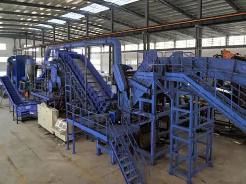
Before placing outlets, decide where ferrous metal, non-ferrous metal and rejects will be collected. Each fraction needs a route to that point. A scrap sorting conveyor could serve separation. A metal recycling discharge conveyor could take a recovered fraction to collection. The scrap metal conveyors specification covers these duties without prescribing models or an outlet count.
Put the receiving equipment, size range, flow and outlet elevation beside each discharge point. Use the same drawing to show cross-mixing controls and the response to a full bin or stopped collection. If the route turns or changes elevation, mark the change where the last conveyor hands material to its receiver. This scrap metal conveyors specification stops there; site-wide space and traffic go in the layout plan.
Before requesting a quote, settle interface questions in the scrap metal conveyors schedule. For scrap metal conveyor systems, trace type, drive, capacity, guarding and controls to the material and receiver. State supplier assumptions; mechanical, electrical and site teams should approve boundaries.
| Interface field | Buyer input or required supplier response |
| Material and duty | Feed mix, maximum piece and batch weight, bulk density, target and peak flow |
| Infeed | Loading method, impact point, elevation, shredder opening, oversize handling |
| Transfer | Outlet and inlet elevations, piece size, accumulation point, receiving-stage limits |
| Discharge | Fraction, destination, container or next process, collection interruption |
| Protection and controls | Guarding, access, stop signals and restart responsibility for qualified review |
| Commercial boundary | Conveyor and chute supply, installation, testing, drawings and acceptance owner |
MAXIM machinery can configure an integrated line's crushing, conveying and separation for the feed and required outputs. The schedule checks the proposed scrap metal conveyor and its protection against this project's inputs; neither should be assumed standard. Send material samples or photos and a marked drawing with the completed schedule to MAXIM machinery. The quote should state any remaining assumptions and exclusions.
A: A direct connection depends on the separator accepting the shredder's discharge form and flow. Check size distribution, peak rate, relative heights and feed presentation. A buffer or metered feeder may still be needed to steady the handoff. Put the route and the response to a separator stop on a drawing, then validate it with representative material.
A: State the scrap mix, bulk density, normal throughput and peak rate. Give the dimensions and weight of the largest expected piece. At each handoff, say how material arrives, what receives it, where the route rises or turns and where the fraction ends up. Include site access and interface ownership. The supplier can use that sheet for a proposal. Have an engineer check load ratings and safety design.
A: No. A scrap conveyor belt is one option, subject to the feed and loading conditions. Compare belt and chain-plate options with other surfaces against sharp edges, heavy or irregular pieces, batch loading and drop impact. Ask the supplier to justify the surface choice, including how it will be protected and maintained. Confirm the choice with an equipment engineer before placing the order.
A: The receiving bin or next machine determines much of the discharge interface. Name the fraction being carried, then give its size range and normal and peak flow. Mark the outlet height, direction and clearance on the drawing, along with the response to a full bin or stopped collection. Where several fractions leave the line, show separate destinations and any point where they could mix.
A: Look for two mismatches: the upstream stage sends material faster than the receiver can take it, or piece shape and chute geometry allow bridging. The drawing should show the drop, receiving width, access and accumulation zones. Qualified mechanical and controls designers need to settle stop and restart responsibilities; a generic layout is not a safety design.
Trace scrap from loading to collection before choosing conveyors. A correctly sized shredder can still wait for feed or stop when discharge backs up. Scrap metal conveyors need a handoff specification across feeding, transfer and discharge. For each interface, record the material condition, receiver, route and stop response. Put the scrap mix and required line excerpt …
